
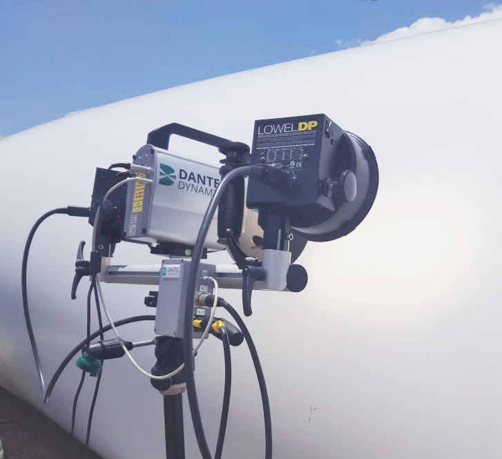
DANTEC Dynamics Laser Shearography system in action, inspecting a wind turbine blade for defects, deployed by CICNDT for non-destructive testing (NDT).
Laser Shearography: An NDT Tool for Advanced Composite Structures
A detailed look into the application, advantages, limitations, and future trends of laser shearography for non-destructive testing of composite boat hulls, aerospace materials, rocket bodies, and aircraft.
Laser shearography has emerged as a powerful and versatile non-destructive testing (NDT) method, offering significant advantages for the inspection of composite materials across various high-performance industries. This optical technique provides a full-field, non-contact, and high-speed solution for detecting subsurface defects like delaminations, disbonds, and voids that could compromise the structural integrity of critical components. Driven by demands for faster and more reliable inspection, the technology is rapidly evolving with advancements in hardware miniaturization, robotic automation, and artificial intelligence (AI). This report delves into the principles of laser shearography, its key characteristics, its comparison to other NDT methods, its specific applications, and the technological trends shaping its future.
The Principles of Laser Shearography
At its core, laser shearography is an interferometric technique that measures the first derivative of out-of-plane surface displacement, which is directly related to surface strain. The process involves illuminating the surface of a test object with a coherent laser beam, which creates a unique speckle pattern because the surface is optically rough. This pattern is captured by a camera equipped with a shearing device that splits the image into two and slightly displaces, or “shears,” one with respect to the other. These two sheared images interfere on the camera’s sensor, creating a reference interferogram.
This “self-referencing” or “common-path” design, where one part of the image acts as the reference for the other, is a key advantage over traditional holography. It eliminates the need for a separate, isolated reference beam, making the system significantly more robust and less sensitive to environmental vibrations and rigid body motion.
To reveal defects, the object must be subjected to a small amount of stress, which is a fundamental operational requirement. This stress causes the surface to deform, and areas above subsurface defects will deform differently than sound areas. After the stress is applied, a second interferogram is captured. By digitally subtracting the two interferograms, a “shearogram” is generated, which displays fringe patterns representing the gradient of the out-of-plane surface deformation. Anomalies in these fringe patterns, which often appear as “butterfly” or “bulls-eye” shapes, indicate high concentrations of surface strain, revealing the location and size of subsurface defects like delaminations, disbonds, voids, or impact damage.
Stressing Techniques for Defect Detection
The selection of an appropriate stressing method is critical for a successful inspection, as it must induce a non-damaging deformation that highlights the defects of interest. The choice depends on the material, component geometry, and the type of flaw being sought.
Thermal Loading
Principle: This method involves applying a slight, uniform temperature change (e.g., 3-10°C) using heat guns or infrared lamps. Subsurface defects like voids or delaminations act as insulators, disrupting the normal thermal expansion and causing localized surface deformations. A specific form, microwave heating, can be used to detect trapped moisture in nonmetallic composites.
Advantages: It is a non-contact method that can be applied rapidly over large areas and is effective for a wide range of defects, including disbonds and impact damage.
Disadvantages: Applying heat uniformly can be challenging, and excessive heat can potentially damage sensitive materials. Effectiveness also depends on the thermal properties of the material and the defect.
Selection Criteria: Well-suited for inspecting composite laminates, honeycomb structures, and bonded repairs, especially for near-surface defects that disrupt thermal flow.
Vacuum or Pressure Loading
Principle: This technique involves enclosing the part (or a section of it) in a vacuum chamber or under a portable vacuum hood and reducing the pressure. Air trapped in defects like disbonds or delaminations expands under vacuum, creating a distinct blister-like deformation on the surface. Conversely, internal pressurization can be used for components like pressure vessels.
Advantages: This is considered the most effective and reliable method for detecting disbonds, delaminations, and core damage in honeycomb and foam-core sandwich structures, as it provides a very uniform load.
Disadvantages: It may require a vacuum chamber, which limits the size of the part, though portable vacuum hoods are widely used for inspecting large structures in the field.
Selection Criteria: This is the preferred method for many aerospace components (control surfaces, radomes) and marine structures (boat hulls) made of sandwich composites where trapped air in defects can be exploited.
Vibration or Acoustic Loading
Principle: The test object is excited with vibrations using a shaker or non-contact acoustic energy from a loudspeaker. Subsurface defects alter the local stiffness of the material, causing them to vibrate with different amplitudes and phases than the surrounding sound areas. This differential vibration reveals the flaw.
Advantages: This dynamic method is excellent for detecting disbonds and cracks, particularly in stiff structures or where flaws are difficult to excite with static loads.
Disadvantages: It can be more complex to set up, often requiring a sweep through various frequencies to find the optimal one to excite a defect.
Selection Criteria: Often used for inspecting solid laminates, bonded metallic structures, and welded joints where a dynamic response can effectively highlight a loss of stiffness.
Key Characteristics and Considerations
Advantages
The key advantages of laser shearography make it highly suitable for inspecting large composite structures:
- High-Speed, Full-Field Inspection: It allows for the rapid inspection of large areas, significantly faster than traditional point-by-point scanning methods like ultrasonic C-scans. Automated systems can achieve inspection throughputs as high as 1,000 square feet per hour, compared to roughly 10 square feet per hour for some ultrasonic methods.
- Non-Contact Nature: The method avoids physical contact with the part, eliminating the need for a coupling medium (like water in UT) and preventing surface contamination. It is also versatile for complex geometries.
- Structural Significance: Shearography measures the material’s mechanical response to stress, meaning it primarily reveals flaws that affect the structural integrity, minimizing focus on purely cosmetic issues.
- Reduced Sensitivity to Environment: Its self-referencing design makes it relatively insensitive to environmental vibrations and rigid body motion, making it suitable for both factory and in-field inspections.
Technical and Operational Limitations
Despite its strengths, shearography has notable limitations that are actively being addressed by new technologies.
Defect Detection and Characterization
- Dependency on Deformation: The method can only detect flaws that produce a measurable surface deformation under the applied stress. Defects that are too deep, do not enclose a volume of air (for vacuum stress), or do not alter the mechanical response will go undetected.
- Limited Defect Typing: While excellent for disbonds and delaminations, it struggles to characterize other critical defect types like fiber breakage, matrix cracking, or microscopic damage.
- Quantitative Complexity: Providing qualitative images of flaws is straightforward, but quantitative analysis to determine a defect’s exact size and depth can be complex and may require other NDT methods for confirmation. This requires advanced phase-shifting and unwrapping algorithms to process the data.
- Complex Geometries: Curved and complex shapes can make it difficult to apply uniform stress and can complicate the interpretation of the resulting fringe patterns.
Dependency on Material Surface Properties
- Surface Roughness: The method requires an optically rough surface (at least one wavelength of light) to generate a stable speckle pattern. Smooth, specular, or highly reflective surfaces may require surface preparation, such as applying a temporary, washable developer spray.
- Translucent Materials: Materials like marble or some unpigmented composites are challenging because light can penetrate the surface and reflect from within, causing speckle decorrelation and a poor response.
Level of Expertise for Data Interpretation
- Operator Dependency: The successful application of shearography has traditionally been highly dependent on skilled personnel. The interpretation of the resulting fringe patterns can be subjective, time-consuming, and prone to human error, potentially creating a bottleneck in production.
- Addressing the Bottleneck with AI: This limitation is being mitigated by sophisticated software incorporating Artificial Intelligence (AI) and Machine Learning (ML). Modern systems feature Automated Defect Recognition (ADR) to process fringe patterns in real-time. Deep learning models are being trained to automatically classify defects, remove data artifacts, and even estimate impact energy, significantly reducing operator subjectivity and enhancing reliability.
Comparison with Other NDT Methods
The choice of an NDT method depends on the specific application, material, and types of defects being targeted.
Laser Shearography vs. Ultrasonic Testing (UT)
| Feature | Laser Shearography | Ultrasonic Testing (UT) |
| Primary Principle | Measures mechanical response (surface strain) to an applied stress. | Detects internal material inconsistencies using high-frequency sound waves. |
| Defect Detection | Excellent for disbonds, delaminations, and “kissing bonds.” Less effective for deep flaws, fiber breakage, and micro-cracks. | Can identify a wide range of surface and subsurface anomalies, including smaller and deeper defects. Phased Array UT is adept at handling anisotropy in composites. |
| Characterization | Provides qualitative images of strain concentration; more indicative of a flaw’s structural significance. Quantitative analysis is complex but improving with AI. | Can provide detailed information on the size, shape, and depth of defects, but may flag inhomogeneities that are not structurally critical. |
| Operational Constraints | Requires external stress and an optically rough surface. Automated systems are extremely fast, with rates of 100-500 sq ft/hr. | Often requires a couplant (gel or water) and physical contact. Point-by-point scanning can be slow for large areas (e.g., 10 sq ft/hr). |
| Expertise | Traditionally requires high expertise, but AI-driven software is automating interpretation. | Highly dependent on operator skill for signal interpretation. |
Laser Shearography vs. Infrared Thermography (IRT)
| Feature | Laser Shearography | Infrared Thermography (IRT) |
| Primary Principle | Measures a material’s mechanical response to an applied stress, revealing defects that alter local stiffness. | Measures a material’s thermal response to heat, revealing defects that alter thermal conductivity. |
| Defect Detection | Provides sharp indications of bonding integrity. | Effective for near-surface defects. Detectability is limited by the ratio of defect diameter to depth. |
| Characterization | Quantitative analysis is complex. AI is being used to fuse shearography and thermography data for more comprehensive analysis. | Generally restricted to near-surface imaging. Quantitative depth analysis is possible by analyzing thermal transit time. |
| Operational Constraints | Requires an optically rough surface but is unaffected by surface emissivity. | Highly sensitive to variations in surface emissivity, which can be misinterpreted as defects and may require surface painting. |
| Expertise | Requires a skilled operator to select the stressing method and interpret fringe patterns, though AI is reducing this burden. | Thermal images are generally more intuitive to interpret than shearograms, but expertise is still needed. |
Applications in Composite Boat Hulls
The marine industry increasingly uses advanced composites like Fiber Reinforced Plastics (FRP) and carbon fiber sandwich structures to build lighter, stronger, and more efficient vessels. Laser shearography is a practical and effective solution for inspecting these large structures, both during manufacturing and for in-service damage assessment.
Modern yachts and high-performance boats often feature advanced sandwich constructions with carbon fiber skins over a honeycomb or foam core. The inspection procedure for these large hulls typically involves portable, vacuum-attached shearography systems. These units can be locked onto the hull surface, making them immune to the motion of the boat, which allows for inspection in a variety of environments, from the factory floor to the shipyard.
For stressing, a vacuum hood attached to the inspection head creates a localized vacuum on a section of the hull. This slight pressure change is sufficient to cause subsurface defects to deform the surface, revealing them to the camera. Thermal stressing is also commonly used to find defects like impact damage. Modern systems can inspect large areas quickly, with rates of 5 to 10 square meters per hour being common.
The technique is highly effective at detecting critical defects that can compromise the hull’s structural integrity, including:
- Core-to-skin disbonds
- Delaminations
- Impact damage, including Barely Visible Impact Damage (BVID)
- Voids in the core material or bonding layers
- Cracked or crushed cores
Applications in Aerospace and Aircraft
The aerospace industry was an early adopter of shearography, driven by the need for reliable, high-speed inspection of advanced composites.
Pioneering Role: The B-2 Stealth Bomber
Laser shearography’s entry into industrial NDT was marked by its critical role in the production of the U.S. Air Force B-2 Stealth Bomber. In 1987, the first production shearography NDT system was delivered to Northrop Grumman for the B-2 program, representing the first major application of the technology on a production aircraft.
The B-2’s design relies heavily on complex composite structures to achieve its stealth capabilities. Traditional NDT methods like ultrasonic C-scans, with inspection speeds of around 10 square feet per hour, were too slow for the required production rates. Shearography offered a revolutionary alternative, with inspection rates of 100 to 500 square feet per hour. Large gantry systems housed within vacuum chambers were used for 100% inspection of bonded composite surfaces. By slightly reducing the chamber pressure, trapped air in subsurface defects would expand, causing a minute surface deformation that the system could detect. This allowed for rapid feedback to correct manufacturing processes and was highly effective at finding critical flaws such as disbonds, delaminations, and core damage in composite honeycomb structures.
General Aerospace Applications
Today, shearography is crucial for both manufacturing quality control and in-service maintenance of aircraft like the Airbus A350 and Boeing 787.
Aerospace Materials and Components Inspected:
- Composite Laminates: Used in fuselages, wing skins, and empennage structures.
- Honeycomb and Sandwich Structures: Found in control surfaces (flaps, rudders) and radomes.
- Composite Repairs: Ensuring the integrity of bonded patches.
- Helicopter Blades: Automated systems are used for both inspection and repair processes.
Production-level systems are often integrated into large gantry or robotic setups for automated inspection. Shearography cameras are mounted on gantry systems, robotic arms, and collaborative robots (“cobots”) to perform automated, repeatable, and highly accurate scans of aircraft fuselages, wings, and helicopter blades. This enables Computer-Aided Inspection (CAI), where scan paths are automated and multiple images are stitched onto a 3D model of the part for precise defect localization. For maintenance, portable units can be vacuum-attached directly to an aircraft for in-hangar inspections. The method is adept at finding disbonds, delaminations, voids, core damage, and “kissing bonds”—where surfaces are in contact but have no adhesive strength.
Applications in Rocket Bodies and Space Systems
The extreme reliability requirements of the space industry make NDT a critical part of the lifecycle of launch vehicles and spacecraft.
Composite Rocket Bodies and Motor Casings
Shearography is used to inspect large composite structures like launch vehicle payload fairings and cryogenic fuel tanks. For solid rocket motors, it is used to verify the integrity of the bond between the propellant and the motor casing, which is crucial for safe operation. Stressing techniques include thermal loading, vacuum, and acoustic excitation. It has also been used to find disbonds in the metallic bonds of coolant channels in liquid propellant rocket engines.
Composite Overwrapped Pressure Vessels (COPVs)
COPVs, which consist of a thin metal liner overwrapped with a high-strength composite, are used to store high-pressure fluids. Shearography provides a reliable method for inspecting the composite overwrap for manufacturing defects or in-service damage. The vessel is typically stressed by slightly altering the internal pressure or by applying gentle heat. This is effective at finding defects such as delaminations, disbonds between the liner and overwrap, fiber bridging, and ply wrinkling, all of which could lead to catastrophic failure.
A Critical Case Study: The Space Shuttle’s External Tank (SOFI)
A landmark application of shearography was the inspection of the spray-on foam insulation (SOFI) on the Space Shuttle’s external tank. Following the Columbia disaster, which was caused by foam breaking off during launch, NASA required an improved inspection method. Vibration shearography was specifically developed to inspect the bond-line of the SOFI. The foam was subjected to vibrations at specific frequencies, causing defect areas with poor bonding to resonate and deform differently from well-bonded areas. The system was highly effective at detecting “kissing bonds,” voids, and other disbonds between the foam and the aluminum tank. Despite challenges related to the tank’s large size and complex geometry, the method proved sensitive enough to detect debonds with a diameter approximately half the thickness of the foam.
Technological Advancements and Future Trends
The field of laser shearography is undergoing rapid evolution, driven by hardware miniaturization, robotics, and AI.
Hardware Improvements
Systems are becoming more compact, powerful, and portable. Companies offer lightweight, modular systems designed for field use on aircraft and boats. These systems feature high-resolution, low-noise cameras capable of measuring nanometer-scale deformations, paired with powerful lasers to ensure high-quality data.
Automation and Robotics
The integration of robotics is revolutionizing large-scale inspections. Shearography cameras are mounted on gantry systems, robotic arms, and collaborative robots (“cobots”) to perform automated, repeatable, and highly accurate scans of aircraft fuselages, wings, and helicopter blades. This enables Computer-Aided Inspection (CAI), where scan paths are automated and multiple images are stitched onto a 3D model of the part for precise defect localization.
Sophisticated Software and AI
AI is the new frontier, automating data analysis that was once a manual, expert-driven task.
- Automated Defect Recognition (ADR): Software now automatically processes fringe patterns to identify defects in real-time and can stitch images together for comparison with CAD files.
- Deep Learning: AI models like Convolutional Neural Networks (CNNs) are being trained to classify defect types, estimate quantitative parameters like impact energy, and remove data artifacts.
- Solving the Data Bottleneck: To train these AI models, researchers are using Generative AI to create synthetic defect data and developing weakly supervised learning methods that can automatically generate high-quality annotations from raw shearography images, dramatically reducing manual labor.
Executive Summary
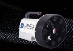
Dantec Dynamics Laser Shearography system deployed by CICNDT for advanced non-destructive testing (NDT) applications.
Laser shearography is a highly effective and efficient non-destructive testing method for a wide range of composite structures. Its ability to provide rapid, full-field, and non-contact inspection makes it an invaluable tool in industries where safety and reliability are paramount.
-
- For composite boat hulls, its portability and speed enable the thorough inspection of large sandwich structures, ensuring the integrity of high-performance marine vessels by detecting core-to-skin disbonds and impact damage.
- In the aerospace industry, shearography is a mature technology that was pioneered on the B-2 bomber program. Today, robotic automation enables high-throughput inspection of large components for both manufacturing quality control and in-service maintenance.
- For rocket bodies and space systems, it provides a reliable means of detecting critical defects in thermal protection systems (like the Space Shuttle’s SOFI), composite overwrapped pressure vessels (COPVs), and other large composite structures, helping to ensure mission success.
The effectiveness of shearography is continually improving as technology addresses its traditional limitations. While its performance depends on a defect’s ability to cause surface deformation, advancements in automation and artificial intelligence are making the technique faster, more reliable, and less dependent on operator expertise. The integration of robotics has dramatically increased inspection speed, while AI-driven software is automating the complex task of data interpretation. As the use of advanced composites grows, the role of laser shearography as a cornerstone of modern, intelligent NDT will continue to be critical.