

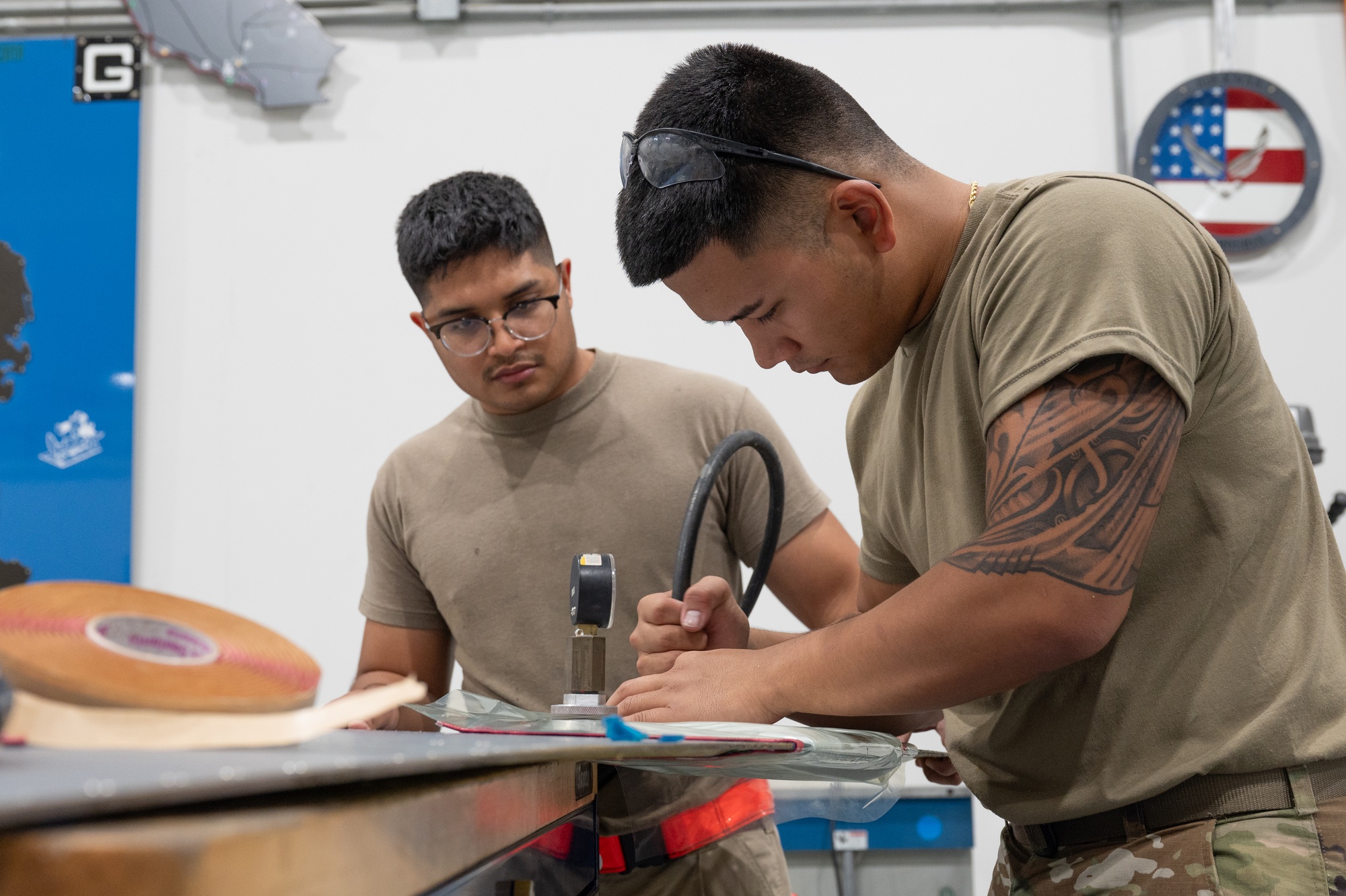
A composite repair can look smooth, follow the correct contour and still contain a hidden discontinuity. Non-destructive testing (NDT) lets inspection teams examine a repair without cutting into the structure, which makes it a central part of composite repair inspection. But every inspection answers a narrower question than many people assume: whether the chosen technique, applied under defined conditions, shows indications of the conditions it was set up to find.
That distinction matters most at a bonded interface. A scan may reveal a disbond or a void, but a clean scan on its own does not prove that the bond has the required strength. For aerospace and other critical structures, inspection works best as one part of a larger body of evidence that starts with surface preparation and ends with a decision by the responsible engineering authority.
Start with the part, the defect and the decision
Before selecting a method, define the material and construction, the location and geometry of the bondline, the defect types of concern and the access available. A thin laminate repair on a solid skin is a different inspection problem from a repair on a curved sandwich panel. Coatings, tapers, adhesive thickness, core and surface condition can all influence the result.
Also define what the result will be used for. Is the goal to locate a disbond, map impact damage, check a completed repair or investigate an unusual indication? Detection, sizing and acceptance are different tasks. The applicable engineering requirements and approved procedures set the acceptance criteria, not the inspection method.
Disbonds and weak bonds are different problems
A disbond is a separation or lack of contact at a bonded interface. Depending on its size, depth, geometry and access, a disbond can produce a response that a suitable NDT procedure is able to detect.
A weak bond may show no obvious separation even though adhesion or strength is inadequate. Weak bonds include so-called kissing bonds, where the surfaces are in close contact but carry little load. Surface contamination, incorrect materials and process deviations are commonly cited causes. Conventional NDT should not be relied on to find weak bonds or to measure bond strength directly. A NASA-funded research summary on nondestructive evaluation of adhesive bond strength notes that conventional techniques “have proved unable to ensure detection of weak bonds or quantitatively measure bond strength.” An industry working-group report on structural bonding submitted to the FAA reaches a similar conclusion and describes post-bond inspection as “necessary, but not sufficient” evidence that a bond was made correctly.
Shearography works differently: it looks at how the surface deforms under an applied load rather than how sound passes through the part. Because an interface with no adhesion responds differently under stress, shearography can reveal kissing bonds in many cases. No method directly measures bond strength.
The practical takeaway: prevent bond-quality problems through process control during the repair, then use a validated inspection to look for the conditions the procedure can detect. A clean image or a single instrument reading does not replace process records or approved acceptance criteria.
Choosing methods for composite repair inspection
No single method suits every part or defect. The options below are general starting points for procedure development, not performance claims.
| Method | Where it can help | What to consider |
|---|---|---|
| Visual inspection | Surface damage, repair contour and visible anomalies on accessible surfaces. | Does not establish subsurface condition on its own. |
| Ultrasonic testing (ultrasonics) | Widely used to look for delaminations, disbonds, porosity and voids, and can provide depth-related information in many laminates. | Material attenuation, thickness, curvature, access, coupling and suitable reference standards all affect results. |
| Bond testing (resonance, pitch-catch, mechanical impedance) | Often used on bonded and sandwich structures to look for disbonds and delaminations. | Results depend on skin thickness, construction, defect depth and representative reference standards. |
| Active thermography | Area-based thermal imaging that can help reveal some near-surface anomalies. | Heating method, thermal properties, depth, geometry and surface condition affect what can be seen. |
| Laser shearography | Full-field imaging of surface deformation under an applied load, such as vacuum or heat, that can help reveal disbonds, delaminations and kissing bonds. | Loading method, part constraints, surface condition and environmental stability affect results and interpretation. |
| Computed tomography (CT) | Three-dimensional internal information for suitable parts or representative samples. | Part size, material, resolution and equipment access can limit practical use. |
One practical approach is to use an area method to flag regions that warrant a closer ultrasonic look, provided both methods have been shown suitable for that component. That is a planning example, not a required sequence. Published research also shows that ultrasonic results in composites depend on probe configuration, frequency and material attenuation, so results from one specimen should not be treated as general detection limits.
Build an evidence chain around the repair
A useful inspection plan connects the scan to the work that produced the bond:
- Define the repair and the damage. Record the part, construction, repair location, damage extent, applicable instructions and access limitations.
- Control surface preparation. Follow the approved cleaning, abrasion, handling and contamination-control steps, including any required hold points.
- Document the bonding process. Keep the applicable adhesive identification, shelf-life, environmental, vacuum or pressure, and cure records.
- Inspect to an approved procedure. Use qualified personnel, appropriate reference standards, defined coverage, and documented settings and data-quality checks.
- Record and route the results. Document locations, findings and limitations, and send indications and any incomplete coverage to the responsible engineering authority under the applicable requirements.
The FAA’s advisory circular on quality systems for the manufacture of composite structures (AC 21-26A) describes manufacturing controls, such as surface cleaning, bondline thickness and cure records, that are useful background for bonded work. Each program must confirm which regulations, customer specifications, approved repair data and acceptance criteria actually apply.
Questions to ask before approving the inspection plan
- Which defect or damage types must the procedure detect, and where could they occur?
- Are the repair geometry, materials, thicknesses and access represented in the reference standards or validation specimens?
- How will coverage, coupling or loading, and data quality be checked and recorded?
- What are the method’s documented limitations, including weak bonds and inaccessible areas?
- Who has the authority to evaluate indications and decide whether the repair meets the applicable requirements?
These questions turn an equipment choice into an inspection plan that can support a defensible decision.
How CICNDT can help
CICNDT supports composite NDT through inspection services, method selection, procedure development and training. Every engagement starts with the component, the defect of concern and the applicable requirements; evaluating indications and accepting a repair remain with the responsible engineering authority. Explore our composite NDT inspection and consulting services, see our composite NDT training, or contact CICNDT to discuss a part, a repair or a feasibility study.
This article is general information. It does not replace approved repair data, inspection procedures, engineering disposition, or applicable regulatory and customer requirements.
References
- NASA Space Technology Research Grants, “Nondestructive Evaluation of Adhesive Bond Strength by Ultrasonic Phase Measurements” (2016 fellowship project summary). nasa.gov
- Transport Airplane Metallic and Composite Structures Working Group, “Recommendation Report to FAA: Structural Bonding” (Final, July 29, 2021). faa.gov
- FAA, Advisory Circular 21-26A, “Quality System for the Manufacture of Composite Structures” (July 23, 2010). faa.gov
- Taheri, H., and Hassen, A. A. (2019). “Nondestructive Ultrasonic Inspection of Composite Materials: A Comparative Advantage of Phased Array Ultrasonic.” Applied Sciences, 9(8), 1628. doi:10.3390/app9081628
Featured image: U.S. Air Force photo by Senior Airman Alex Lowe. The appearance of U.S. Department of War (DoW) visual information does not imply or constitute DoW endorsement.